During the operation of pipe belt conveyors, the torsion of round pipe conveyor belts often occurs. The reasons for the torsion include the following:
1. The new conveyor belt just put into use has a large resistance, making the conveyor running in an unstable state.
2. Due to prolonged use, deformation or wear of the mechanical parts and grounding of the conveyor belt overlapping parts occur.
3. The accuracy of the manufacturing or installation of the polygonal roller group and its supporting structure is not sufficient.
4. The deformation of the conveyor belt in the curved section.
5. The accuracy, elasticity, rigidity and hardness of the conveyor belt are not uniform.
6. Misalignment of the conveyed material in the circular conveyor belt.
7. Partial wear of the roller.
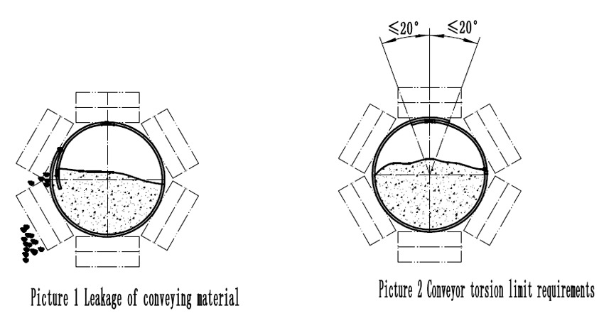
When the torsion of the circular conveyor belt is serious, many unexpected situations will occur. For example, leakage of material being transported (Picture 1); accelerated wear of conveyor belts and idlers; increased power consumption; conveyor belt edges inserted into the idler gap of a polygonal idler group, or by the structural guide chute stuck, causing the conveyor belt torn or structural damage. Therefore, it is necessary to adjust the twist of the round pipe conveyor belt.
Of course, no twisting is impossible, and under normal conveying conditions it is possible to convey twists with a small angle. Once the conveyor is started, the overlap of the conveyor belt must be monitored with the structural frame of the conveyor as a reference, and the alignment of the conveyor belt at the head and tail of the conveyor should be monitored if the overlapping position of the conveyor is clockwise relative to the structure. If the counterclockwise rotation is more than 20° (Picture 2), the belt must be adjusted. It is recommended that it should not exceed 30° under any circumstances.
Torsional control is particularly important for conveyor belt conveyors near the head-to-tail transition section, as the twisting of these two round-pipe conveyor belts will cause severe runaway of the conveyor belt as it rolls in and out of the drum, causing accidents. occur. There is very little ideal state without twisting or twisting at all. Therefore, the length of the drum of a round belt conveyor is usually longer than that of a universal belt conveyor.
However, for a long conveyor belt conveyor, the torsion of the circular conveyor belt at a distance from the head and tail transition section can be adjusted according to the actual situation. If the lap joint seal can ensure that the material does not leak, And can maintain the normal forward running state, can return to the required centering state when the head and tail transition section, ensure that the deviation is within the normal range, then the torsion of the section of the circular tube conveyor belt during the operation can not be taken Special adjustments.
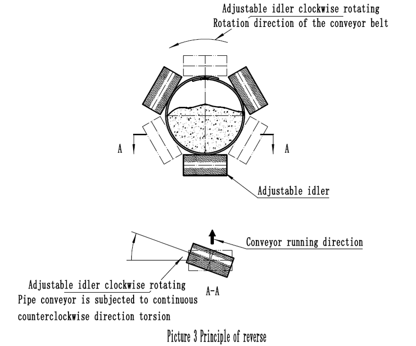
The principle of correcting the deviation of the universal belt conveyor can be adjusted at the edge of the conveyor belt. It can also adjusted by the same method as the forward idler roller. Picture 3 shows the schematic diagram of the twisting principle. By adjusting the angle of the roller clockwise or counterclockwise, the endless conveyor belt receives a constant counterclockwise or clockwise torque correction. The adjusting roller is usually set at the lower roller of the polygonal roller group which bears a large pressure.
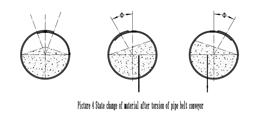
The situation of the state of the conveyed material after the torsion of the circular tube conveyor belt is shown in Picture 4. The conveyor belt with a smaller angle twisted has a tendency to recover under the action of the material center.
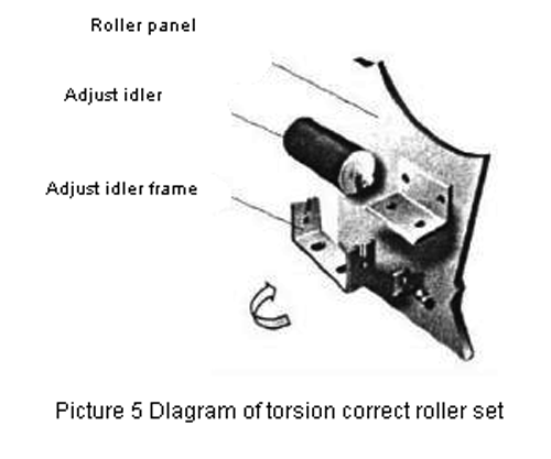
Picture 5 shows the structure of the parts and their positional relationship for the adjustment roller group of Picture 3.
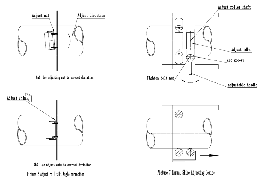
Picture 6 shows how to use the adjustment nut and adjust the spacer to correct the deviation. According to the requirements, any idler can be selected as the idler, the idler to be adjusted is selected, the tightening nut is loosened, and then the tightening nut is adjusted or the gasket is adjusted to tighten under the tightening nut, then the idler is changed As a "backward idler roller" to adjust the role of the roller.
Picture 7 shows another manual adjustment of the roller assembly. In order to facilitate the operation, this positive roller is installed in front of the polygon roller and its panel. The roller can be rotated around its vertical axis. The operator can adjust the roller according to the need, rotate and adjust the roller, when adjusted to the appropriate position. After tightening the compression nut to fix its position, the adjustment of the idler can continue to impose a torsional force on the conveyor belt of the round tube to achieve the purpose of adjustment.
The method of manual adjustment is not enough for the long-distance round belt conveyor. It must be adjusted automatically to correct the normal operation of the conveyor.
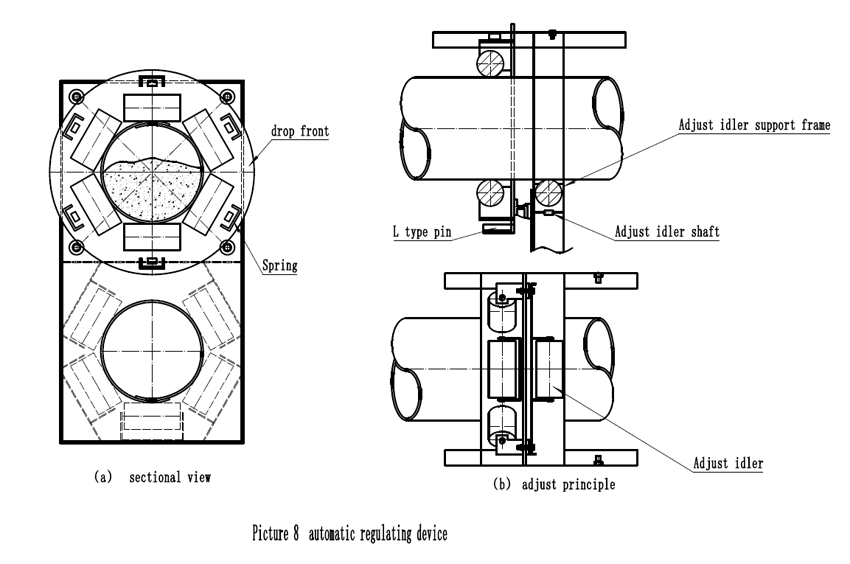
In Picture 8, the hexagonal roller set is mounted on a movable panel that can be rotated along the support roller of the movable panel. The spring on the hexagonal roller serves to press the roller against the conveyor belt. {Picture 8-25(a) }, When the conveyor belt is twisted, the moving panel rotates, and it adjusts the roller support to rotate around its vertical axis through the L-shaped pin (Picture 8-25(b)) to adjust the running direction of the roller and the conveyor belt. Rotating at a certain angle produces a torsion force opposite to the twisting direction of the conveyor belt, thereby gradually adjusting the conveyor belt back to its normal state.
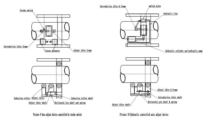
Picture 9 shows the automatic adjustment device with stroke switch control and electric push rod operation. When the conveyor belt is twisted, the induction roller will move along its vertical axis. The horizontal pin and spring will make the induction roller press the conveyor belt to enhance the hair processing. When it is twisted to a certain angle, the induction roller bracket will touch the stroke. The switch activates the electric push rod, and the electric push rod adjusts the idler to rotate around its vertical axis by adjusting the idler support, so that the rotational direction of the adjusted idler is at a certain angle with the running direction of the conveyor belt, and the correct twisting force is generated on the conveyor belt. To achieve the purpose of adjustment.
According to the above-mentioned twisting principle, there are some similar methods. Picture 10 shows a hydraulically controlled adjusting roller device. The induction roller is driven by the torsion conveyor belt and activates the hydraulic valve driven by the on-off valve to drive the hydraulic cylinder. The hydraulic cylinder then drives the adjustment roller to a position that is at a certain angle with the running direction of the conveyor belt to generate a torsional force that prevents the conveyor belt from continuing to twist.
It should be noted that if the above-mentioned automatic adjustment method is adopted, it is necessary to ensure that each installation automatically adjusts the roller device to be in a proper position before operation, and continuously corrects it in the debugging stage, otherwise, it will not achieve a correcting effect, but instead conveys it. With twisting intensified. Actual use can be combined with a variety of methods in order to achieve better operating results.


