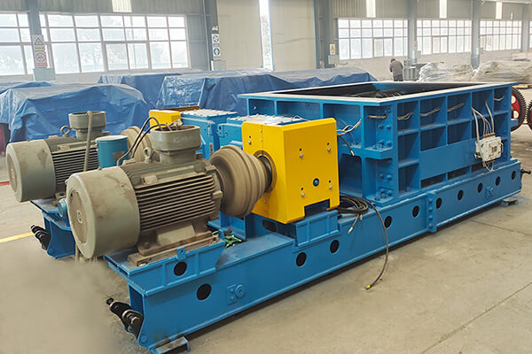
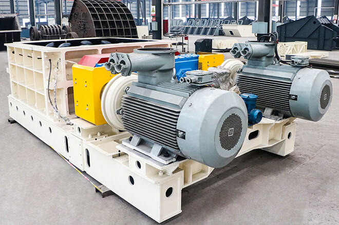
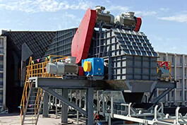
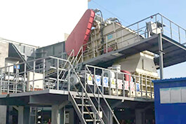
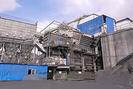
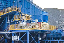
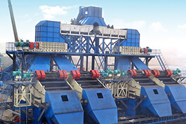
Mineral sizers are widely used in coal mining, metallurgy, building materials and many other fields. The working principle is that two crushing rollers with roller teeth rotate opposite each other and rely on the mesh of the roller teeth to shear and squeeze the material to complete the crushing of the material. As the core components of mineral sizers, crushing rollers include crushing teeth and other components, which are the key to achieve safe and reliable operation of the whole machine, so the processing accuracy, installation accuracy, vibration and other requirements are high. At the same time, the span of the crushing roller is large, and the transverse vibration generated in the working state will have an adverse impact on the shaft, bearing and other important components to reduce their service life, and the transverse vibration of the crushing roller can cause the shaking of the whole machine, affect the performance of the whole machine, and reduce the crushing efficiency. Therefore, the vibration of the crushing roller should be considered to provide a theoretical basis for calculating the strength, stiffness, allowable vibration energy level of the equipment and structural optimization of the whole machine.
.jpg)
1. Motion equation of crushing roller
1.1 The crushing roll model was established by finite element method
In order to analyze the dynamics of
mineral sizers crushing roll by finite element method, the finite element model of crushing roll must be established. In general, we use rigid disk, elastic shaft containing mass, elastic support and other components to describe the rotor of rotating machinery and divide the rotor into disk, shaft segment, elastic support and other units along the direction of the axis of rotation, use nodes to connect each unit and use discrete matrix description, and select the location of each node on the center of the disk, axis and bearing seat. The finite element coordinate diagram of the rotor is shown in figure 1. through this coordinate system, the axis coordinates of any axial cross-section of the rotor can be calibrated: deflection angle of the cross-section 0, 0, and rotation angle p, and the displacement of any cross-section is expressed as [xb,j, [yb.1.
1.2 Differential equation of crushing roller motion
In this paper,
mineral sizers crushing roller is taken as the analysis object. Its structure is 5 rings, 4 teeth and 5 rings are closely connected together to form a chain structure vibration system. Therefore, the mass of the whole system is discretized and a series of elastic elements are added to construct a lateral vibration system with concentrated mass. The main shaft of the crushing roll with 5 tooth rings can be regarded as an elastic shaft, and the crushing roll can be simplified into a model consisting of a rigid disc, an elastic shaft unit and an elastic support unit with concentrated mass. According to the above description of the rotating subsystem and the deduced motion equations of the disk unit, the elastic shaft unit and the elastic support unit, the motion equation of the crushing roll can be obtained.
Vibration analysis of mineral sizers crushing roller under normal working conditions, the external force of mineral sizers crushing roller is mainly the impact force caused by the collision between the crushing teeth and the material, and the angular speed of the crushing roller is ωo, so the periodic impact force is generated. The impact frequency produced by the crushing roller has two, one is produced by the action of four roller teeth on a single tooth ring, and the other is produced by the joint action of five tooth rings. From the rated speed of the crushing roller 24r/min: (1) there are 4 roller teeth on each ring, and the resulting impact frequency w is: ω1=4 24=1.6(s1)(7) 6(2) the roller teeth on the adjacent ring are arranged in a spiral shape, separated by 18°, the resulting impact frequency is equivalent to 5 times that of ω1: w2=5×4× 24=8.0(s1)(8) 60 the values of ω1 and w2 are compared with the obtained natural frequency, and it is found that ω, is close to the third order natural frequency, while the value of ωw is far from the natural frequency. Therefore, the main vibration form of the crushing roller is the third-order vibration mode, which is mainly caused by the impact of the four roller teeth and materials on the single ring.


.jpg)
