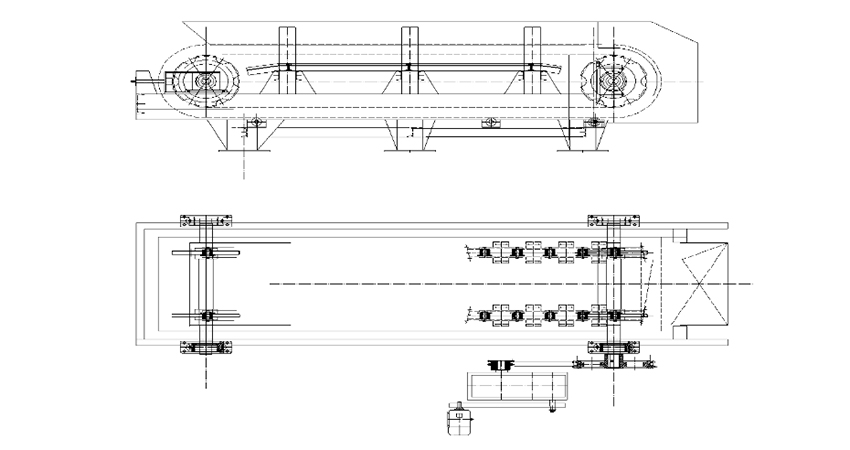
It is crucial and important to
installation and commissioning, the user must need to understand the installation order and commissioning process that he would operate the
correctly without mistakes. What’s more, understand its characters would greatly your work efficiency.

1.Preparation and inspection before installation
1.1Check the quality acceptance reports and material analysis reports of the key parts such as chains, and all of them shall meet the requirements of the corresponding drawings.
1.2Check whether the assembly of the chain is consistent with the requirements.
1.3Check whether the roller can run flexibly, and the installation position and quality of sprockets should be consistent with the requirements of the drawing.
1.4Before installation, the
apron feeder of the assembly parts should be check whether the parts are corroded or damaged. If there is any problem, the installation shall be allowed only after re-repair, cleaning and refueling.
1.5Carefully check through the position measurement at the installation site, and the basic dimensions of each device and frame must be the same as those marked on the drawings.The problem should be dealt with in time, and the parts can only be placed after all dimensions are correct.
2.The installation order and adjustment of the
apron feeder
2.1The frame sections shall be installed after welding on site, and check the welds whether its strength have no effect on the frame.
2.2
Apron feeder tail tension device
In most cases, it is better to install the tail tension device at first and adjust the spring tension to the required position as the drawing.
2.3 Apron feeder head unit
2.4 Apron feeder drive unit
2.5
Apron feeder running part
The running part must be installed after the transmission is adjusted and the cement filling is solidified. When installing the trough, pay attention to the direction of its operation, and do not reverse it. When installing or replacing the chain plate, the chain plate and the track chain are bolted. The tightening torque of each bolt is 750-900N·M.
Install in the order described above. There should be enough space in the tail to facilitate the installation of the running part.
3.The installation requirements of the
apron feeder
3.1Underframe
a. The straightness of the underframe is 1/1000; the tolerance along the longitudinal length is <±4mm:
b. The diagonal difference of the underframe is 1/1000, and the tolerance is <6mm along the longitudinal length:
c. The deviation between the centerline of the underframe and the longitudinal centerline of the machine body is ±2mm.
3.2
Apron feeder roller, carrier sprocket
a. The parallelism of the support wheel generatrix in the horizontal direction of the frame and the horizontal plane shall not exceed 1/1000 of the width of the chain plate.
b. The parallelism of the carrier wheel busbar in the horizontal direction of the frame and the horizontal plane shall not exceed 1/1000 of the width of the chain plate.
3.3
Apron feeder head, tail device
a. The verticality of the sprocket axis to the longitudinal centerline of the frame shall not be greater than 1/1000 of the span of the two bearings of the sprocket.
b. The parallelism between the axis of the sprocket and the horizontal plane shall not be greater than 1/1000 of the span of the two shafts of the sprocket.
3.4
Apron feeder running part
a. Chain assembly in groups of 48 pitches, connected in the field;
b. The chain must be at the running-in stage and the conveyors are evenly loaded before installation. When assembling, ensure that the side gap of the tank is 4mm and the bottom clearance is 5mm;
c. The fasteners (bolts, nuts) used for the connection between the trough plate and the chain link must be tightened, and the tightening torque is 430 N·m;
d. The direction of overlap of the trough plates is consistent with the marked operation of the running section.
3.5
Apron feeder tail tension device
a. The deviation between the center line of the tail shaft and the longitudinal center line of the body is 1 mm;
b. The horizontal deviation of the center line of the tail wheel shaft is 1 mm;
c. 350 is the limit position size of the tensity. When the chain elongation is close to 350, the chain length of the pitch (P=216)×2 is required to be adjusted;
d. The parallelism between the tension axis and the water level shall not be greater than 1/1000 of the two bearings.
4. Commissioning
4.1 Examination before start-up
a. There should be sufficient lubricating grease in all bearings, transmission parts and reducers;
b. The chain and the sprocket mesh normally, without deviation;
c. The gap between the conveying trough is uniform, and there is no jamming or interference phenomenon;
d. The roller can rotate flexibly without abnormal noise;
e. The bolt connection is reliable, especially no looseness among the bolts with the chain connecting and the conveying trough;
f. The tension device of the adjusted screw should rotate flexibly;
g. No lubrication leakage at all points;
h. The bearing temperature rise does not exceed 35 ° C, the maximum temperature is not higher than 65 ° C. The temperature rise of the reducer does not exceed 45 ° C;
i. At 5 mm from the
apron feeder, the average noise of the no-load operation is measured to not exceed 80 dB.
j. Record voltage, current and power values.
4.3 Load operation
After the no-load started, it can be gradually fed the material. It takes 48h of running load before normal operation. When the load is running, in addition to the inspection items for no-load operation, the following inspections and records shall be made.
a.It is preferred to operate at a speed of 0.06-0.075 m/s. Intermittent operation is allowed when there is less fed. The feeding material needs to be uniform, avoiding the large block material to punch the tank body which protect it from the deformation and deflection.
b.No leakage or scattering.
c. Record voltage, current and power according to the specified time.


